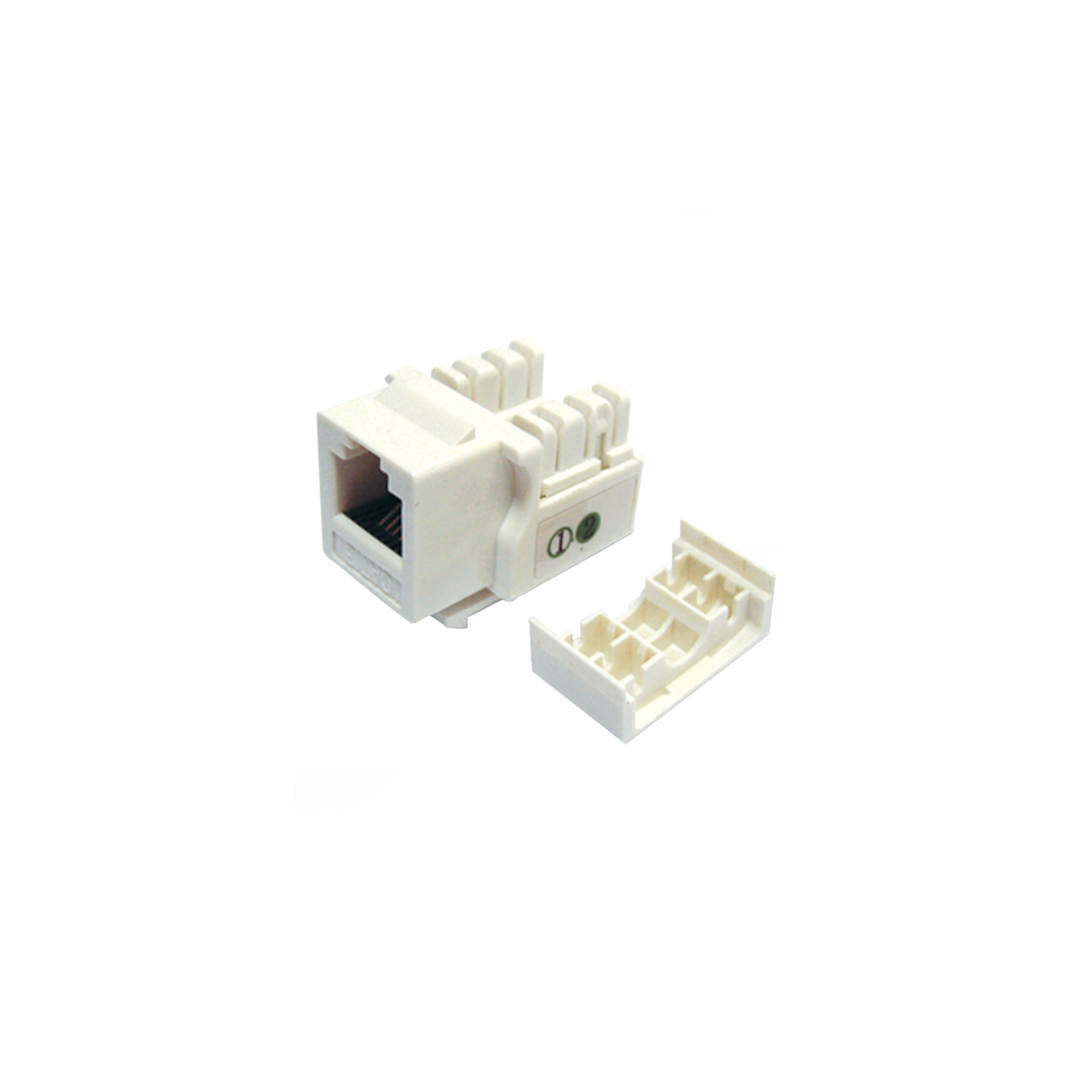
CAT.3 UTP Keystone Jack
Part Number:
PL-KE3UJ
Categories: Copper Cable System, Keystone Jack
- Category 3 unshielded 90° keystone jack for 1 to 16 MHz Class C voice and low-speed data cabling applications.
- 8-position modular interface populated with four contacts; the approved pin assignment governs application compatibility.
- Dual IDC termination accepts 110 or Krone-style impact tools when permitted by the released installation instruction.
- Accepts 22-26 AWG solid copper conductors; CCA and CCS conductors are excluded. Stranded conductors require separate qualification.
- Compact keystone form factor for compatible unloaded faceplates and patch panels; final fit is controlled by the released dimensional drawing.
- High-impact polycarbonate housing with UL 94 V-0 material rating for the released resin grade.
- Modular mating contacts use 50 microinch gold over nickel; IDC contacts use the released nickel-plated phosphor-bronze construction.
- Minimum 750 modular mating cycles; Category 3 transmission performance shall be supported by a released component report through 16 MHz.
CHARACTERISTICS
| Property | Specification |
| Product type | Category 3 UTP 90° keystone jack; unshielded modular interface |
| Category / bandwidth | Category 3 connecting hardware; 1-16 MHz; Class C system use |
| Interface / contacts | 8-position modular jack with 4 fitted contacts; pin assignment per released drawing |
| Housing | High-impact polycarbonate (PC); UL 94 V-0 material rating for the released resin grade |
| Mating-contact material | Phosphor bronze with nickel underplate |
| Gold-plated contact area | 50 microinch (1.27 micrometre) gold over nickel in the modular mating area |
| IDC contacts | Phosphor bronze with minimum 100 microinch (2.54 micrometre) nickel plating, per released BOM |
| Conductor compatibility | 22-26 AWG solid copper; conductor and insulation diameters per released termination drawing; CCA/CCS excluded |
| Termination method | 110 or Krone-style impact tool, subject to the released installation instruction |
| Dielectric strength | 1000 V RMS for 1 minute, subject to released test verification |
| Current rating | 1.5 A maximum per contact, subject to released test verification |
| Insulation resistance | Minimum 10 megohm; test voltage and environmental conditions shall be stated in the released report |
| Initial contact resistance | 2 milliohm nominal per contact; the released report shall state the maximum acceptance limit |
| Operating temperature | -10°C to +60°C |
| Relative humidity | 10% to 90%, non-condensing |
| Mating durability | Minimum 750 insertion/removal cycles; post-cycle contact performance verified by the released test plan |
| IDC retermination | Permitted reuse and cycle limit governed by the released qualification report and installation instruction |
| Environmental | RoHS-compliant released material set |